A Review on the Platform Design Dynamic Modeling and Control of Hybrid Uavs
1. Introduction
Aerial flight has been a topic of sheer interest from time immemorial since the Wright brothers built the first manned aircraft in 1903. Still, recent developments in lightweight blended materials, compact and reliable electronics, and robust flying controller algorithms have made the technology accessible to the research, educational, and programmer communities. UAVs accept created a tremendous bear upon on society by calculation a new perspective to the way that nosotros expect at things, equally they has revolutionized agriculture and farming by the application of NDVI (Normalized Deviation Vegetation Index) imaging and pest command [1], remote inspection, and strategic disaster management operations through the application of image processing and object detection [2], mapping, surveillance, constabulary enforcement, social distancing, and reconnaissance operations by providing aerial footage of the region of interest for target acquisition [three].
With the applications of UAVs catering to such widespread areas, in that location has been an undeniable need for hybrid UAV configurations. UAVs take been categorically divided into 3 basic configurations: fixed-wing aircrafts, multi-rotors, and blimps or aerostats. Each of these configurations has advantages, limitations, and applications of their ain. Yet, in recent times, research has identified various hybrid frameworks that lie at the intersection of these configurations.
One among such hybrid platforms is the VTOL stock-still-fly shipping or hybrid UAV with thrust vectoring capabilities, which could potentially address the limitations and finer couple the advantages of both the rotorcraft and fixed-fly shipping. The ability of having a dual flight envelope makes information technology ideal for complex missions where both the speed and flight endurance of the fixed-wing aircraft and hovering, ambitious maneuvering, and vertical takeoff/landing capabilities of a multi-rotor are needed [4].
These hybrid subclasses of UAVs have been studied and analyzed in the past few years due to their enormous utility [5,half dozen]. They are further classified based on their transition mechanism between two contained flight profiles enabling them to accept a dual flight envelope. We used such studies as a backbone to come up upwardly with the conceptual sketch for our prototype pattern. The hybrid platform of tilt-rotor UAVs has been primarily classified into ii primary categories as follows:
- (i)
-
Tail-sitters: This configuration takes off and lands vertically on its tail and undergoes the transition from vertical to horizontal level flight mode by differential thrust or actuation by control planes. Due to their ability to achieve level flight without any extra actuators, they turn out to be mechanically simple just pose a complex problem in command and structural design, as they demand to withstand periodic impact loads on their rear tails, which is undesirable for a miniature UAV, as in our case [7].
- (2)
-
Convertiplanes: Different the tail sitters, convertiplanes maintain their shipping configuration integrity throughout the flight envelope (i.e., the fuselage is level in both flight modes) and employs the tilting of the subcomponents such as a morphable wing, motor orientation, etc., to attain seamless transfer between contained flight modes [8]. Depending on the subcomponent responsible for the transition, convertiplanes are once again subcategorized into:
- (A)
-
Dual System Tilt-Rotors: This configuration utilizes multiple actuators, which are directed upwards and down in a pusher tractor configuration [ix]. Even so, this subsystem is piece of cake to pattern and model, as both flight modes tin exist analyzed separately. However, carrying actress actuators tin reduce overall efficiency due to the decreased payload carrying capacity and an increase in propeller downwash. One of the main reasons for prototyping such a hybrid VTOL vehicle was to increment the endurance, and carrying boosted actuators posed a blueprint penalisation to such an objective.
- (B)
-
Rotor wing/Finish rotor: Some other bio-inspired design of the hybrid convertiplane is the rotor-fly, where the rotating wing generates lift for hovering, and after gaining a particular altitude, it decelerates and subsequently stops its motion to act similar to a stock-still-wing shipping to cruise larger distances hence the name end-rotor. This design is best optimized in terms of structural efficiency as information technology ensures the complete utilization of the fly, which is one of the most significant components in terms of weight and size in whatever stock-still-wing UAV. Nevertheless, this idea of reducing the number of redundant components is essentially a tradeoff, as it has demanding blueprint requirements. One of these challenges or constraints is that the wing needs to have an elliptic profile for maximum lift distribution. It is required to be symmetrical to balance out the aerodynamic forces and moments [10]. The transition from a fully rotating wing in the VTOL phase to an inactive fixed-wing phase will create a gyroscopic moment and add together to the challenges in attitude controller design. Finally, even though both of the forces required for the motion are different, i.east., rotational for the VTOL phase and translational for the fixed-fly stage, they demand to be generated from the same frame, which makes the entire trouble quite intricate [xi]. Due to the above-mentioned challenges, the conceptual idea of designing a mono-copter rotor wing was not deemed feasible, every bit a de-spin platform or an agile rotating tail too needed to be designed to make information technology stable during the transition phase, which would add together to the complication and would increment the power consumption of the entire pattern.
- (C)
-
Tilt Wings: This subcategory, equally the name suggests, achieves seamless transition past tilting the entirety of both wings with a motor fixed to them. Every bit the motors remain stock-still to the wings, dynamic modeling is simplified by adopting a wing fixed reference frame [12,thirteen]. However, in hindsight, as the wing is directed vertically upwards during hovering, landing, and takeoff, the motor adds boosted elevate and makes the aircraft unstable due to its inherent susceptibility to crosswinds and gust disturbances.
- (D)
-
Tilt-Rotor: The tilt-rotor concept is identical to that of tilt wings, where multiple rotors are mounted on the shaft or nacelles at the cease of the wingspan. This solution shows promising potential, as actuation can be achieved with a minimum of two actuators, unlike dual arrangement convertiplanes, leading to an increase in payload carrying capacity and a reduction in wing loading, as changing the orientation of the rotor shafts leads to the transition without affecting the structural integrity of the vehicle, unlike tail sitter UAVs, and is more than robust and adaptable to crosswind condition, unlike tilt wings [5,12]. Few pattern concepts of VTOL tilt-rotors have been explored in the past, but the major enquiry focus of past researchers was on the quad-copter or tri-copter blueprint [14,xv] and the conceptualization of robust control schemes for flight transition [xv,sixteen,17]. However, this paper focusses on achieving the aforementioned thought with a minimum number of actuators and on formulating mathematical modelling that will help in robust control scheme implementation.
Hence, we went frontward with the VTOL tilt-rotor design with dual rotors to reach optimal performance with minimum actuation after exploring the various pattern alternatives, every bit shown in Figure one. Another attribute of the design was the point of actuation where the brushless DC motors are mounted on the nail, which seemed to be reasonable, as information technology reduces the aerodynamic interference between the propellers and wing and also ensures a compatible and shine airstream flow over the fly. The conceptual design of the VTOL tilt-rotor with a pair of counter-rotating actuators was finalized with the objective of achieving an efficient hybrid vehicle in terms of aerodynamics and overall weight. However, this blueprint adds to the complexity in modeling and controller design, as the entire flight profile can at present be divided into three dissimilar phases, i.e., the VTOL hover phase, the transition phase, and the horizontal fixed-wing flight phase. Not only do the flight phases in the entire flying profile alter, but the functionality of the control surfaces and the actuators also vary in each of these independent flight profiles. Because an example of the axisymmetric differential thrust of the actuators, differential thrust in the hover phase leads to the curl motion of the fuselage axis of the vehicle. All the same, in the horizontal fixed-wing flight phase, differential thrust produces a yawing motion at the vertical axis. Hence, these challenges in design, modeling, control, simulation, and fabrication volition be addressed sequentially in this newspaper.
This paper discusses the conceptual design and fabrication of a novel hybrid VTOL tilt-rotor to accost the endurance limitation in rotorcrafts and the landing and takeoff strip requirements in fixed-fly aircrafts. The objective of the design is to address the claiming of achieving optimal performance using minimum actuation and past achieving flight stability by implementing control in all independent flight modes. This concept of thrust vectoring with dual actuators tin as well exist implemented as a fail-safe mode in multi-copters where a pair of counter-rotating propellers tin can lead to a safe landing in case of failure without inflicting any harm to the concrete environment. Similarly, the tilting ability of the actuators can also aid to vary the assault angle of a hybrid stock-still-wing UAV in order to achieve an optimum thrust to weight ratio for larger cruise distances.
The residual of the paper is organized as follows: Department 2 provides the mechanical design of the conceptualized hybrid UAV, and Section 3 emphasizes the principles of operation past that information technology is able to achieve under actuated motion in air. Kinematic and dynamic modelling of the hybrid UAV is discussed in Department iv. Finally, controller blueprint and experimental results are discussed in Section 5 followed by the decision and future work.
2. Mechanical Design
The initial blueprint of the hybrid VTOL tilt-rotor is conceptualized on two prior key ideas, which were identified as a pattern necessity, i.e., the minimum weight and the maximum efficiency in terms of aerodynamics. Hence, it is designed with ii actuators that turned out to be the minimum number of back up actuation points without introducing any additional complication in the controller design. The two actuators are mounted on the fly boom with the help of custom-made rotor mounts and can be tilted independently by the actuation of loftier torque metal servos. Mounting actuators on the fly boom proved benign, as the design was symmetrical at the fuselage, with both actuators on either side of the CG (center of gravity). The CG of the entire hybrid platform is at the midpoint of the wing blast, which simplified the blueprint.
The fuselage is placed underneath the CG and could be used as a housing motel to nest all of the flying avionics and electronics. The conventional tail acts like to an extension of the fuselage with horizontal and vertical stabilizers. Both of the actuators present on either side of the wing can exist operated in the vertical orientation for the VTOL flight stage and can exist later on tilted by servos to the horizontal orientation used in the stock-still-wing flight phase.
Hence, the mechanical design of the hybrid VTOL tilt-rotor consists of four major parts, i.e., the wing, the fuselage, the tail, and the rotor with a tilt machinery. An isometric schematic view of the components in the hybrid VTOL tilt-rotor forth with its respective inertial (XE, YE, ZE) and body (XB, YB, ZB) reference frames is shown in Figure 2.
Due to rotating nacelles, the wing demanded an aerofoil cross-section to accept the least amount of CM (coefficient of pitching moment) variation, with a change in the attack angle preventing stalling and maximizing CL/CD to ensure an increase in endurance and a polish transition between two independent flight profiles. Hence, a high wing configuration with a DAE 51 aerofoil cantankerous-section was chosen after comparing several other possible symmetrical and unsymmetrical airfoils in XFOIL [18]. Both the fly and the fuselage are supported and held together past custom-designed brackets with square aluminum rods. Custom motor mounts were also designed, where both the motor and high torque servos could be housed in a single compartment, and two coaxial spur gears would enable the tilting motion of actuators.
However, there were few shortcomings in the first blueprint that needed to exist addressed. Hence a second iteration of the design was conceptualized. The first minuscule change was the change in the configuration of the tail from an H to an inverted T. This minor change was due to the effectiveness of the command surface that was only present in the stock-still-fly flight phase. This minor change with a slight shift in the position of the flight avionics led to a reduction in weight, every bit a shorter fuselage stout could now be used. The earlier design of the tilt-able rotor mount, a similar version of which was besides implemented by Tom Stanton [nineteen], was meaty and elegant but had severe problems backlash bug in the spear gears. Hence, a second rotor mountain was designed without the gears for the tilting mechanism, equally illustrated in Figure three.
The third and final iteration incorporated the landing gears, which were placed underneath the CG so that carrying the payload did not bear on the flight dynamics. Here, both the landing gears and the payload are mounted in such a manner that the middle of mass of the overall system is lying on the same centrality with the center of mass of the payload and the landing gear. Hence, mounting of payload volition innovate a vertical offset in the CG of the overall system along the boost axis without causing any change in the overall inertial terms. Table i shoes all of the critical design parameters based on the mechanical design. The overall dimensions, the centre of gravity, and inertial terms were derived from the CAD design, equally shown in Figure 2.
3. Principle of Performance
Beingness a hybrid framework of the multi-copter and conventional stock-still-fly aircraft, the working principle of a hybrid VTOL tilt-rotor is quite similar to that of a multi-copter with slight variation in each of the independent flying phases. Information technology has six degrees of freedom, out of which 4 are independent (boost, pitch, roll, yaw) and 2 are coupled (surge and sway). Hence, it is not possible to achieve surge and sway motion independently without any curl and pitch input. The position and mental attitude of the unabridged hybrid VTOL tilt-rotor is controlled by continuously varying the collective athwart velocity and the deflection of the thrusters. Equally the unabridged flying envelope is divided into 3 definitive phases, i.e., the VTOL hover phase, the transition stage, and the fixed-wing cruise phase, the working principle is summarized in each of the independent phases as mentioned beneath.
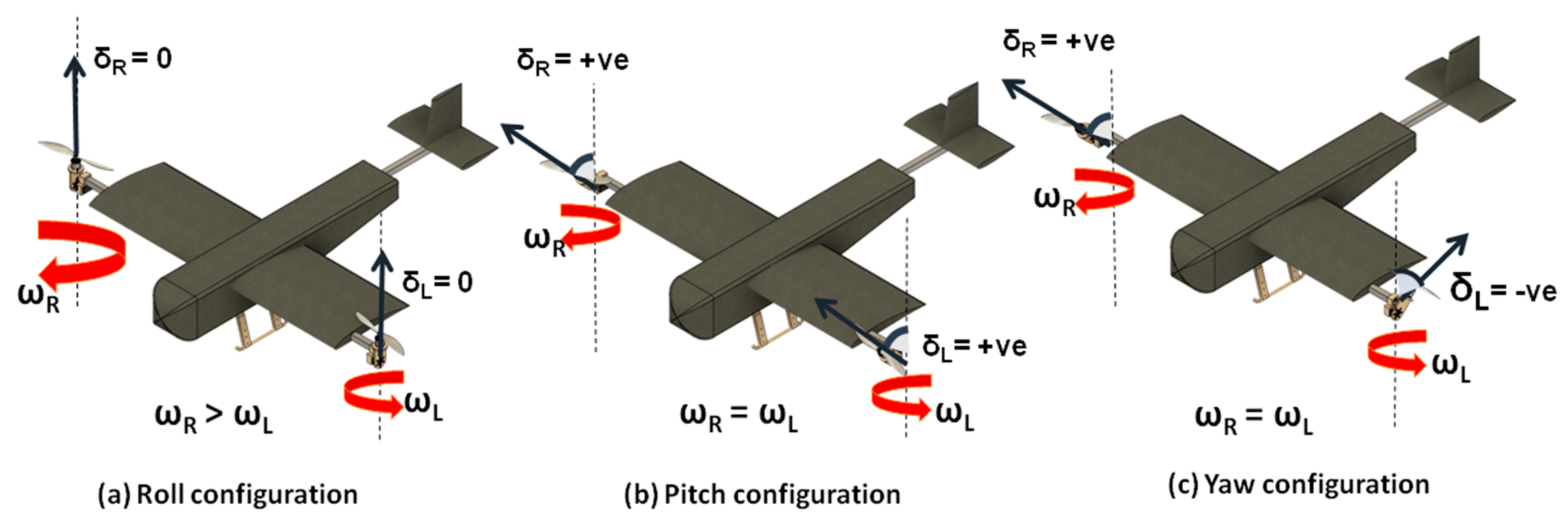
(i) VTOL or Hover Stage: During takeoff, landing, and hovering movement, the hybrid platform is in the VTOL phase. In this phase, the thrusters (combination of actuator and propeller) are in the vertical orientation. Heave motion with an centrality pointing onto the plane, as shown in Figure i, is achieved by increasing or decreasing the angular velocity of the two rotors proportionately. Roll motion (coupled with sway motility) is achieved by increasing the angular velocity of one thruster with respect to the other thruster. Hence ringlet right motion is obtained past increasing the angular velocity of the left thruster with respect to the correct thruster. Pitch and yaw movement are a more challenging, as they are not but controlled past varying the athwart velocity of the thrusters but too by the deflection of the individual motor pods. Pitch-upwards motion is achieved past tilting the thruster towards the nose, which creates a moment and a horizontal component of thrust force, leading to surge motion. Similarly, yaw movement is generated by tilting the actuator in opposite directions, which creates a couple of CG due to the horizontal component of the thrust being directed in contrary directions for both the thrusters. A representative figure demonstrating the working of the hybrid VTOL tilt-rotor in each independent flying phase is shown in Figure four.
(two) Transition Phase: Later on attaining a particular altitude, the vehicle undergoes a transition where both of the rotors change their orientation from a vertical alignment to a horizontal alignment. As in the VTOL phase, the vehicle's entire weight is supported by the collective thrust of the actuators, while in the stock-still-wing phase, the lift from the wing accounts for the weight. Hence during the transition, a slight dip in altitude is expected, and the key idea to achieve a seamless transfer from one flight mode to another is to make the transition tedious, such that by the time the thrusters have horizontal alignment, the hybrid UAV would have attained sufficient horizontal velocity to produce the required lift from the wing to keep the platform airborne. The slight dip in distance is introduced considering of the time interval required for change in thruster direction, which eventually leads to a change in the thrust direction from the vertical heave axis to the horizontal surge axis. Thrust vectoring reduces the actuator force interim along the heave axis, leading to a dip in altitude, which is, again, an actuator limitation, as discussed subsequently in the simulation department.
(3) Fixed-Fly or Cruise Phase: In this flight phase, both thrusters are in horizontal alignment, and the working principle is similar to that of a conventional aircraft. Heave move or variation in altitude is achieved past varying the angular velocity of the thrusters, which, in turn, affects the lift generated from the wing. Scroll motility is controlled by combined input from the ailerons and varying the angular velocity of the rotors, while pitch and yaw motility is controlled past deflecting the elevator and rudder surfaces, respectively. The overall working of the hybrid VTOL tilt-rotor in the iii dissimilar flight phases is summarized in Table ii. In the summarized table, the right motor is labeled as M1, and the left motor is labeled as M2, every bit shown in Figure ii, whereas their angular velocity is denoted past ωR (clockwise) and ωL (counterclockwise). A positive tilt of the motor pod denotes the tilting of the actuator towards the olfactory organ of the aircraft.
4. Mathematical Modelling
In this section, we develop the mathematical model of the hybrid VTOL tilt-rotor based on the forces and moments acting on it. Understanding the dynamics of such a hybrid vehicle not just helps u.s. to codify a reliable and accurate mathematical model for the vehicle, capturing the complete data of the vehicle's pose (position and orientation), merely likewise helps in the development of robust flight control algorithms.
Formulating a unified dynamic model for the hybrid vehicle provides the distinct advantage of modeling the entire flight envelope equally a continuous flight regime, ruling out the complexity of flying mode switching between ii discrete flying profiles and their dynamic models.
four.1. Kinematic Modeling of the Bi-Rotor
For the kinematic modeling of the hybrid VTOL aerial vehicle, two coordinate frames of reference are defined [20], as illustrated in Figure ii:
- (1)
-
Body stock-still frame of reference (TenB, YB, and ZB).
- (2)
-
Earth fixed inertial frame of reference (TenE, YE, and ZE).
The position and attitude of the center of mass of the vehicle with respect to the inertial frame of reference is given by
where Φ, θ, and Ψ are the roll, pitch, and yaw angles, respectively, denoting the orientation of the center of mass using Euler angle representation. The consummate pose of the center of mass of the hybrid vehicle is represented by combining both the position and attitude vectors.
Similarly, any change in the pose of the overall arrangement with the CG at ηEastward would lead to velocity in the inertial frame of reference, which is represented by
where
represents the linear velocity, and
represents the angular velocity of the vehicle with respect to the inertial frame of reference. However, the velocity vector of whatsoever vehicle is measured by sensors mounted in the body reference frame, which can be expressed as
where
and
denote the linear and athwart velocity measured in the trunk-fixed frame of reference.
The kinematic relationship between the velocities in the inertial frame and body-fixed frame of reference is given by the following equation:
which can be rewritten in the matrix form as shown below:
Hither J(η2) is the Jacobian matrix mapping linear and angular velocity in the torso-fixed frame to the inertial frame of reference and is decomposed into J1(ηii) to transform the linear velocity, J2(ηii) to transform the angular velocity, and
, which is a naught matrix. The private decomposed Jacobian matrices J1(η2) and Jii(η2) can be expanded equally follows:
where the abbreviations
are used instead of sin (
) and cos (
), respectively.
4.two. Dynamic Modeling of the Bi-Rotor
The dynamics of the hybrid VTOL bi-rotor is represented by a unified dynamic model, which includes horizontal level flight utilizing the aerodynamic lift and drag forces produced by the wing, vertical flight using the thrust generated past the 2 actuators, and the transition stage, which incorporates a mix of horizontal and vertical flying dynamics.
The non-linear dynamic equations obtained for the hybrid aerial vehicle are derived considering the following assumptions:
- (a)
-
The unabridged airframe is a rigid body, which implies that the altitude between whatsoever 2 points on the aircraft does not modify, which too applies to the propellers.
- (b)
-
The rotation of the globe is negligible in comparison to the acceleration of the aeriform vehicle, making the earth a fixed frame of reference for the inertial reference frame.
- (c)
-
In the body-stock-still frame, XBZB is the plane of symmetry, making the off-diagonal terms in the inertial matrix equal to zero.
- (d)
-
The tilt of the motor pods (δr , δl ) does not affect the mass distribution of the vehicle. Hence, the mass and inertial terms remain unchanged, as expressed in Table 1.
Hither, the 6 DOF dynamic equations for the aerial vehicle in the body-fixed frame of reference is expressed every bit per the Newton–Euler conception as shown [21]:
where
and
are the external forces and moments acting on the CG, m is the overall mass of the airframe, and I is the inertial matrix expressed in the body fixed frame of reference. The total external forces and moments interim on the body can be decomposed into a sum of forces and moments generated by individual components, as shown in the following equation:
The total external forcefulness acting on the body is expressed every bit the sum of the post-obit forces:
is acting on the centre of gravity,
is generated past the rotors acting on the point of actuation, which happens to exist at the terminate of nacelles in our example,
is the elevator strength generated past the wing, and
is the total drag force generated by the aircraft. Due to the external gust disturbances, the force contribution have also been modeled as
. Similarly, the external moment is expressed as the sum of the torques
created by the rotors, the
created past the moment due to elevator and drag forces generated past the wing about the CG, the
which is the moment generated due to the deflection of control surfaces, i.east., the ailerons, rudders, and elevators, which are constructive but in the fixed-wing flight phase, and
, which is created by the gyroscopic effect of the propellers. An important point to note here is that the interference between the motor pod and the propellers are neglected because the point of actuation is at the stop of the wing boom. Additionally, as the major forces considered in the fixed-wing flight phase are the elevator and drag forces, it is safe to consider that the aerodynamic interference has a negligible effect on these terms. Still, these aerodynamic interactions can exist studied by wake vortex or velocity distribution plots in CFD simulation [22] or experimentally by a load cell inside the wind tunnel setup [23].
Forces due to gravity and thrusters are intuitive and easy to grasp. While gravity remains along the Z-centrality, being multiplied with the coordinate transformation matrix to transform it from the inertial frame of reference to a body-fixed frame of reference, other forces need an analytical derivation based on the respective frames and the associated aerodynamic coefficients.
In a similar mode, forces due to thrusters are multiplied with the rotational transformation matrix, which is defined by the tilt angle of the motor pod at the Y -axis, equally shown in Figure 2. The tilt angle is denoted by
for the correct motor pod and by
for the left motor pod, respectively.
In the VTOL flight phase, the issue of aerodynamic forces acting on the hybrid aerial vehicle is negligible, only consecutively with the tilt of motor pods, the wings generate aerodynamic lift and elevate force, which tin can be expressed past the equation [twenty]:
Hither,
is the rotational transformation matrix used to transform the elevator and elevate forces back to the body-fixed frame of reference,
is the wing planform area, and
and
are the lift and elevate coefficient of the DAE 51 airfoil. Here, the dynamic pressure (q), as illustrated in Equation (17), tin can be expressed in terms of the density of air (
) and the airstream velocity
as:
.
The resultant airstream velocity (
) tin be expressed in terms of ascending (
) and cruising velocity (
) as:
, and the effective angle of attack can exist expressed in terms of velocity and the tilt bending,
, as illustrated in Figure 5.
Lift and drag forces are dependent on the coefficient of lift and drag, respectively, and with varying angles of attack in the hybrid VTOL tilt-rotor, there should be an intuitive change in these coefficients, also. In conventional fixed-wing aircrafts, both
,
are plotted for the stock-still angle of flight during cruise conditions. In a rotary wing, blade chemical element theory is utilized to compute the variation in the lift and drag. However, in rotary wings, the variation of the angle of assail is less, equally the rotary-wing assumes pre-stall conditions during flight. Hence, using the conventional mathematical models to discover the variation of
and
will not piece of work because of the pregnant change in bending of attack. Additionally, lift and drag are not but the functions of incident angle of assault and longitudinal velocity simply are also dependent on the vertical ascending and descending velocity.
To analyse this, the ANSYS simulation environment was used to simulate the flight of the aerofoil for variations in the angle of attack. Initially, the fluid medium was discretized with C-type mesh [24], as shown in Figure 6.
After meshing, the purlieus atmospheric condition are defined where the incoming edge of the mesh is defined as the velocity inlet, and the rear terminate is the force per unit area outlet. Corresponding solutions are determined for every design indicate by varying the effective angle of attack in each iteration from −10° to 110° where the mesh motion is set to 0.5 rad/south. The solution plot signifying the variation of
and
with changes in the set on angle is shown in Effigy 7.
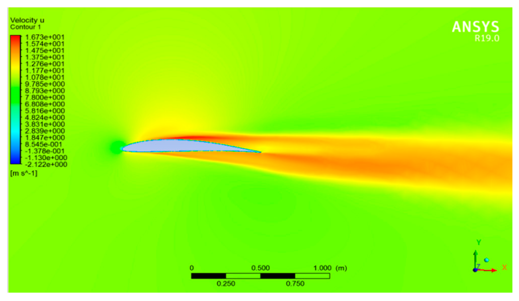
To validate the solution, i of the velocity contour plots for DAE 51 airfoil in cruise weather condition is shown in Effigy 8, which depicts a positive force per unit area potential on the bottom of the aerofoil.
The variation of the lift and drag forces with the change in angle of assail (0–100°) and airstream velocity (0–15 grand/south) is captured in Figure 9. As seen in the figure, a positive elevator force is generated in the fixed-fly flying phase, and a positive drag forcefulness is generated at the VTOL phase due to changes in the angle of attack from 0° to 90°.
Finally, the wind and gust disturbances are modeled equally three-dimensional random sources (3 × 1) in the Simulink surround, which provides random forces for each interval in simulation time, divisional within a magnitude of 0.1 North.
The moment generated past the thrusters is represented past
, which can be mathematically modelled as:
Here,
is the position vector of the betoken of the actuation from the origin, and
is the strength generated by the thrusters. Here, the position vector points to the cease of the wing boom, which simplifies the equation into:
where x = 0.10 m, y = b/2, and z = 0 at the bespeak of the actuation, which is displaced at the ends of the wing boom and is shifted from the CG by the semi wingspan length (b/two).
The aerodynamic moments represented past
occur due to an imbalance of the elevator and drag forces from the CG. Withal, due to the assumption that both the CG and CP coincide with a little deviation along the x coordinates, the aerodynamic moments can be considered to be negligible.
Gyroscopic torque arises when there is a change in the rotation plane of a rotating object. In our case, during the transition, there is a tilt in the motor pods, which leads to the gyroscopic couple interim on the airframe [4], which can be modelled every bit:
where
is the moment of inertia of the motor pod at the rotor axis,
is the rate of change of the motor pod angle, and
is the angular velocity of the rotors.
For a small-scaled UAV moment generated by the control surfaces, information technology can be expressed in terms of wingspan (b), aerodynamic chord (
), and reference area (S) in a like fashion as the lift and elevate forces are derived earlier:
where,
is the dynamic pressure and
,
, and
are the coil, pitch, and yaw aerodynamic coefficients. Hither, the ringlet, pitch, and yaw coefficients tin can besides be expanded as [25]:
Hither, as shown in Equations (22)–(24), the moment coefficients depend on aileron revolt (
), lift deflection (
), rudder deflection (
), the athwart velocity of the torso (
, q, r), the angle of assail (α), the sideslip angle (
, and the airspeed velocity (
). Not only do the control surfaces accept an event on the moment coefficients, but they also take an overall effect on the lift and drag of the airframe. Considering elevators as an example, the down pitching of an lift increases the airfoil'due south disproportion, leading to an increase in the lift coefficient. There is also an effect on the angular velocity of the vehicle on the moment coefficients denoted by
From the above equations, information technology is clear that the bi-rotor's scroll and yaw behavior are coupled as a deflection in the aileron effects on the yawing coefficient, with the opposite only being valid in the fixed-wing flying phase.
More often than not, the aerodynamic parameters for control surface deflections are derived from wind tunnel tests or CFD simulations. Because the difficulties in the CFD and wind tunnel tests, the estimation of the control derivatives for the VTOL tilt-rotor is achieved by utilizing XFLR, which was introduced by MIT in 2019 [xviii].
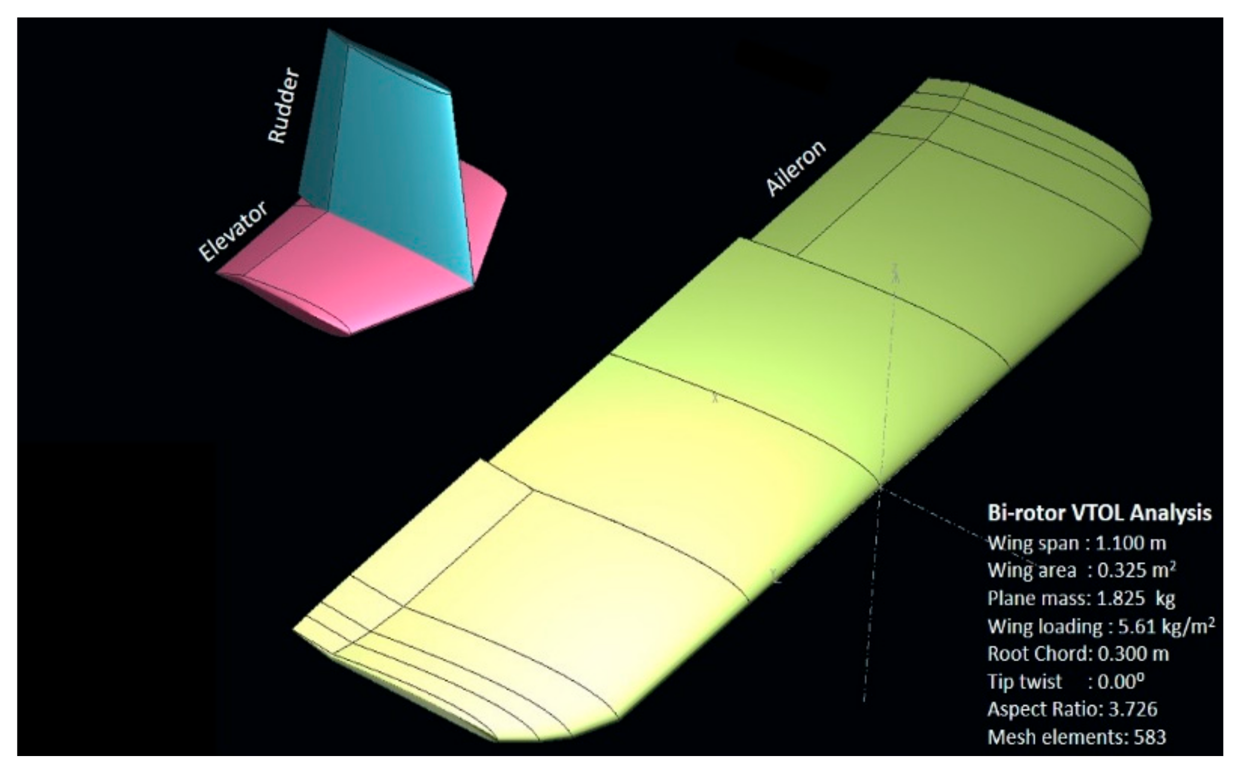
Later modeling the entire VTOL tilt-rotor in XFLR (Figure 10) with a like airfoil profile and mass distribution, the tilt-rotor model, as shown, is simulated for dissimilar control surface deflections (varying from −x degrees to x degrees), varying both the AOA and sideslip angle (varying from −10 to 10 degrees) to approximate the aerodynamic coefficients, and the results are as shown in Figure 11, Effigy 12 and Effigy thirteen.
Considering Figure 11, which highlights the result of aerodynamic coefficients due to elevator deflection, here, nosotros observe that the elevator downward configuration leads to an increase in asymmetry in the airfoil. This asymmetry or camber in the airfoil further leads to an increase in the lift coefficient (CFifty), and elevate existence induced by lift also increases the elevate coefficient (CD). Finally, as shown in the subfigure (d), the elevator down configuration induces an anticlockwise moment on the hybrid aircraft, which is considered negative, while a positive counterclockwise moment is created by the elevator upward configuration.
Similarly, Effigy 12 and Figure thirteen prove the upshot of aileron and rudder on diverse aerodynamic parameters. Here, the effects of rudder deflection are studied based on varying skid deflection, unlike the elevator and ailerons. These varying aerodynamic coefficients are further imported to the Simulink interpolation block for dynamic modelling
The master deviation that can be noticed from such an analysis is that in the neutral configuration, the change in the aerodynamic coefficients is negligible. Hence, different the conventional fixed-wing vehicles, the tilt-rotor utilizes the differential actuation and tilt of the motor pods to accommodate the loss in degree of freedom due to the two actuators in the neutral VTOL configuration, while in the stock-still-wing configuration, the command surface is effective for a change in the orientation of the hybrid aerial vehicle, as shown in the XFLR simulations. Conventionally the aerodynamic parameters are derived experimentally from wind tunnel experiments [26], analytically past DATCOM [27], or from computational simulations which is implemented in this paper.
5. Simulation and Assay
After modeling the non-linear dynamics in the MATLAB Simulink environment, the next step was to implement the command compages on the hybrid VTOL tilt rotor. The control architecture's power to achieve steady flight while maintaining the desired altitude and attitude would assistance us verify the robustness of the flying control algorithm on the hybrid vehicle. The control architecture, as shown in Effigy 14, utilizes four standard PID controller blocks to stabilize altitude, curlicue, pitch, and yaw. The four virtual outputs of the control blocks (u1, u2, u3, u4), which can be compared to the iv channels input in conventional miniaturized UAV, i.e., throttle, aileron, elevator, and rudder is further fed into the flight mixer block. The flight mixing block then redistributes the iv virtual command inputs into seven actuator inputs, which are the angular velocity of the rotor ( ωr , ωl ), motor tilt ( δ right, δ left), and control surface deflection ( δe , δa , δr ). For case, the output u1, which is the output of the altitude controller block, translates to a modify in the angular velocity of both the rotors in VTOL mode but, on the other paw, also leads to elevator deflection in fixed-wing flight style.
The flight mixing block is responsible for mapping the virtual control inputs into actuator signals, which are fed into the dynamic model block visualized past the HL20 VR Simulink module [28]. The functioning of the dynamic model with the implemented command system architecture is verified by simulating trajectory tracking for a step response where the model is able to rail the desired trajectory with a maximum permissible error of 0.25 m, as shown in Figure 15.
Similarly, Figure sixteen depicts the attitude of the hybrid vehicle and controller input for the motor pods while tracking the given reference trajectory.
As shown in Effigy 16b, the motor pod undergoes a tilt from 0° to 90°, performing a transition from the VTOL flight stage to the fixed-wing phase, which can too exist verified by the dip in altitude. The tracking of the reference trajectory within the permissible error of 0.25 g while maintaining the specific altitude and attitude verifies the controller's robustness and feasibility.
6. Experimental Trials
An experimental investigation of the individual subsystem was conducted earlier assembling the image of the hybrid vehicle. Preliminary tests were conducted on the propulsion subsystem, which includes the propeller and the actuator setup. These tests were performed to determine the stable operating RPM and to verify whether the overall thrust to weight ratio for the vehicle is greater than i. The experimental setup, as shown in Effigy 17, consists of the thruster mounted on the load cell incorporated with the HX711 load cell amplifier [29]. A data acquisition arrangement (DAS) built on the Arduino Nano platform was used for data drove. Simultaneously, the electric current and voltage readings from the wattmeter were too recorded to notice the overall power consumption.
The setup was used to analyse the 2-bladed APC 9″ × 4.5″ propellers and the 3-bladed CFRP 11″ × three″ propellers mounted on the 1100 KV DC brushless motor and the xiv.6V Li-Po bombardment for the ability supply. At stable operating conditions of 5000 rpm, 11″ × 3″, propellers generated ane.28 kgf thrust with a power consumption of 799.68 Due west. On the other hand, the 9″ × four.5″ propellers generated 1.44 kgf thrust while consuming 585.4 Due west.
Hence, 9″ × iv.5″ CFRP propellers were selected for the prototype, which produced an approximate thrust to weight ratio of 1.5 and a specific thrust ratio (gram/weight), which is amend in comparing to a conventional UAV [30]. Power consumption was also analysed and was compared with that of the conventional quad-rotor and tri-rotor platforms in the existing literature [31], where the hovering efficiency is analytically derived from momentum theory. It was ended that out of all the 12 bachelor conventional aerial platforms, bi-rotors are compact yet efficient because of their low disk loading and greater hovering efficiency.
The design implemented here also incorporates the stock-still-fly aspect to account for the lift of the wing, which will lead to an increase in endurance without compromising the power requirements. One of the intuitive reasons for bi-rotors being an efficient arroyo in aerial flight is the smaller number of actuators, resulting in less inherent power loss associated with each and every component, leading to the greater efficiency of the overall system. Apart from the analytical studies in [31,32], performed experimental static thrust tests also verified the power of the propulsion subsystem to use less power in comparing to the conventional quad-rotor platform.
The initial test platform undergoing a flight transition from VTOL to a stock-still-wing phase is shown in Figure 18. Afterwards the proper selection of the individual hardware components such equally the flight controller [33], propellers, motors, and ESC, the schematic diagram was adamant, as shown in Effigy xix.
The hardware components were laid out as mentioned in the schematic and some minor modifications were made to the initial test platform, and the terminal image with the individual components is laid out in Figure 20. The epitome fabrication was made using polystyrene cream sheets, foursquare aluminum rods, and custom 3D printed ABS mounts.
Preliminary hover trials were conducted on the experimental image for an average flight time of ane min, which verified stable hover ability at an altitude of one-half a meter above the ground, but the flight transitions induced pitch instability.
7. Conclusions and Future Work
This paper has presented a novel design of a hybrid fixed-wing bi-copter with thrust vectoring capabilities to overcome the range and endurance limitations of rotorcraft configuration. The novel design of the tilting motor pod immune a smooth transition betwixt the stock-still-fly and VTOL phases, robust control over yaw, and pitch motions without any need for additional actuators during the VTOL hover phase. The computational simulations helped us to approximate the mathematical model that was further verified using dynamic modeling in MATLAB. The control algorithm implemented on the dynamic model verified the stability of the hybrid UAV in the stock-still-fly, transition, and VTOL phases. In the experimental trials, we have verified the stability of the hybrid vehicle in hover weather condition. In future works, nosotros will explore the possibility of optimizing the angle of attack to maximize the cruise distance, implementing autonomous flight switching algorithms using ameliorate flight controllers to transition from hover to stock-still-wing flight, and performing all-encompassing trials to accomplish stable operating conditions while transitioning between flight modes.
Writer Contributions
Conceptualization, S.P. and Y.S.S.One thousand.; methodology, S.P. and A.T.; software, South.P. and Y.Southward.Due south.K.; validation, S.P., A.T. and Y.South.S.K.; formal analysis, S.P.; investigation, Y.S.S.K.; resource, A.T.; information curation, Southward.P. and Y.Southward.S.K.; writing—original typhoon preparation, S.P.; writing—review and editing, S.P., Y.S.South.K. and A.T.; visualization, Y.S.S.K.; supervision, A.T.; project administration, A.T.; funding acquisition, Due south.P., A.T. All authors have read and agreed to the published version of the manuscript.
Funding
This research received no external funding.
Institutional Review Board Statement
Non applicable.
Informed Consent Statement
Not applicable.
Acknowledgments
The first author would like to thank the Regime of India for supporting the entirety of the research through the PMRF fellowship (Prime Minister Inquiry Fellowship), which helped during the grade of this project. The authors are also thankful to Kumar Surjdeo Singh for his immense support throughout the prototype'due south fabrication and to Professor Joel George for his valuable inputs in mathematical modelling for the hybrid vehicle. The authors would also like to acknowledge the reviewers and editors for their abiding support and valuable feedback.
Conflicts of Interest
The authors declare no conflict of interest.
References
- Maes, Due west.H.; Steppe, K. Perspectives for Remote Sensing with Unmanned Aerial Vehicles in Precision Agriculture. Trends Plant Sci. 2019, 24, 152–164. [Google Scholar] [CrossRef] [PubMed]
- Maza, I.; Caballero, F.; Capitán, J.; Martínez-De-Dios, J.R.; Ollero, A. Experimental Results in Multi-UAV Coordination for Disaster Direction and Ceremonious Security Applications. J. Intell. Robot. Syst. 2010, 61, 563–585. [Google Scholar] [CrossRef]
- Yamazaki, F.; Matsuda, T.; Denda, S.; Liu, W. Structure of 3D models of buildings damaged by earthquakes using UAV aeriform images. In Proceedings of the Tenth Pacific Conference Earthquake Applied science Building an Earthquake-Resilient Pacific, Sydney, Australia, 6–8 November 2015; pp. vi–viii. [Google Scholar]
- Papachristos, C.; Alexis, K.; Tzes, A. Design and experimental attitude control of an unmanned Tilt-Rotor aerial vehicle. In Proceedings of the 2011 15th International Conference on Advanced Robotics (ICAR), Tallinn, Republic of estonia, twenty–23 June 2011; IEEE: Piscataway, NJ, United states of america, 2011; pp. 465–470. [Google Scholar]
- Saeed, A.Due south.; Younes, A.B.; Islam, S.; Dias, J.; Seneviratne, L.; Cai, G. A review on the platform design, dynamic modeling and command of hybrid UAVs. In Proceedings of the 2015 International Conference on Unmanned Aircraft Systems (ICUAS), Denver, CO, United states of america, 9–12 June 2015; pp. 806–815. [Google Scholar]
- Liu, Z.; He, Y.; Yang, 50.; Han, J. Control techniques of tilt rotor unmanned aerial vehicle systems: A review. Chin. J. Aeronaut. 2017, 30, 135–148. [Google Scholar] [CrossRef]
- Rock, R.H.; Anderson, P.; Hutchison, C.; Tsai, A.; Gibbens, P.; Wong, K.C. Flight Testing of the T-Wing Tail-Sitter Unmanned Air Vehicle. J. Aircr. 2008, 45, 673–685. [Google Scholar] [CrossRef]
- Elijah, T.; Jamisola, R.South.; Tjiparuro, Z.; Namoshe, M. A review on control and maneuvering of cooperative fixed-wing drones. Int. J. Dyn. Control 2021, 9, 1332–1349. [Google Scholar] [CrossRef]
- Cetinsoy, Due east. Design and control of a gas-electric hybrid quad tilt-rotor UAV with morphing wing. In Proceedings of the 2015 International Conference on Unmanned Aircraft Systems (ICUAS), Denver, CO, United states, 9–12 June 2015; IEEE: Piscataway, NJ, USA, 2015; pp. 82–91. [Google Scholar]
- Saeed, A.S.; Younes, A.B.; Cai, C.; Cai, G. A survey of hybrid Unmanned Aeriform Vehicles. Prog. Aerosp. Sci. 2018, 98, 91–105. [Google Scholar] [CrossRef]
- Low, J.E.; Win, L.T.S.; Shaiful, D.S.B.; Tan, C.H.; Soh, Thousand.S.; Foong, S. Design and dynamic assay of a trans-formable hovering rotorcraft (thor). In Proceedings of the 2017 IEEE International Conference on Robotics and Automation (ICRA), Singapore, 29 May–3 June 2017; IEEE: Piscataway, NJ, USA, 2017; pp. 6389–6396. [Google Scholar]
- Chen, C.; Zhang, J.; Zhang, D.; Shen, L. Control and flight examination of a tilt-rotor unmanned aerial vehicle. Int. J. Adv. Robot. Syst. 2017, 14. [Google Scholar] [CrossRef]
- Binz, F.; Islam, T.; Moormann, D. Attitude control of tiltwing shipping using a wing-stock-still coordinate system and in-cremental non-linear dynamic inversion. Int. J. Micro Air Veh. 2019, 11, 1756829319861370. [Google Scholar]
- Bin Junaid, A.; Sanchez, A.D.D.C.; Bosch, J.B.; Vitzilaios, N.; Zweiri, Y. Blueprint and Implementation of a Dual-Axis Tilting Quadcopter. Robotics 2018, 7, 65. [Google Scholar] [CrossRef]
- Jeong, J.; Yoon, S.; Kim, S.; Suk, J. Dynamic Modeling and Assay of a Single Tilt-Fly Unmanned Aerial Vehicle. In Proceedings of the AIAA Modeling and Simulation Technologies Conference, Kissimmee, FL, Us, v–9 January 2015; p. 1804. [Google Scholar]
- Yan, X.; Chen, R.; Lou, B.; Xie, Y.; Xie, A.; Zhang, D. Written report on Control Strategy for Tilt-rotor Aircraft Conversion Procedure. J. Phys. Conf. Ser. 2021, 1924, 012010. [Google Scholar] [CrossRef]
- Chen, Z.; Jia, H. Blueprint of Flight Command System for a Novel Tilt-Rotor UAV. Complexity 2020, 2020, 4757381. [Google Scholar] [CrossRef]
- XFOIL Open up Source Software. Available online: https://web.mit.edu/drela/Public/spider web/xfoil/ (accessed on xv June 2021).
- Tilt Rotor UAV past Tom Stanton. Bachelor online: https://www.flitetest.com/articles/podcast-tom-stanton-3d-press-and-airengines (accessed on 15 June 2021).
- Bouabdallah, Due south.; Murrieri, P.; Siegwart, R. Blueprint and Control of an Indoor Micro Quadrotor. In Proceedings of the International Briefing on Robotics and Automation (ICRA'04), New Orleans, LA, USA, 26 April–1 May 2004; Volume 5, pp. 4393–4398. [Google Scholar]
- Fossen, T.I. Handbook of Marine Craft Hydrodynamics and Motion Control, 1st ed.; Wiley: Hoboken, NJ, USA, 2011. [Google Scholar]
- Theys, B.; Dimitriadis, Grand.; Hendrick, P.; De Schutter, J. Influence of propeller configuration on propulsion system efficiency of multi-rotor Unmanned Aerial Vehicles. In Proceedings of the 2016 International Briefing on Unmanned Aircraft Systems (ICUAS), Arlington, VA, U.s.a., vii–x June 2016; IEEE: Piscataway, NJ, The states, 2016; pp. 195–201. [Google Scholar]
- Zhao, D.; Guo, C.; Wu, T.; Wang, W.; Yin, X. Hydrodynamic Interactions between Subclass and Propeller of Podded Propulsor Based on Particle Image Velocimetry Test. H2o 2019, 11, 1142. [Google Scholar] [CrossRef]
- Das, A.; Tiwari, S. Aerodynamics of plunging airfoil in wind gust. Aircr. Eng. Aerosp. Technol. 2018, ninety, 1050–1064. [Google Scholar] [CrossRef]
- Öner, One thousand.T.; Çetinsoy, E.; Sirimoğlu, Eastward.; Hançer, C.; Ünel, Yard.; Akşit, One thousand.F.; Kandemir, I. Mathematical modeling and vertical flight command of a tilt-wing UAV. Turk. J. Electr. Eng. Comput. Sci. 2012, 20, 149–157. [Google Scholar]
- Shen, J.; Su, Y.; Liang, Q.; Zhu, 10. Calculation and Identification of the Aerodynamic Parameters for Small-Scaled Stock-still-Wing UAVs. Sensors 2018, 18, 206. [Google Scholar] [CrossRef] [PubMed]
- DATCOM for Aerodynamic Parameters Interpretation. Available online: http://www.pdas.com/index.html (accessed on xv June 2021).
- NASA HL20 Lifting Trunk Airframe. Available online: https://world wide web.mathworks.com/aid/aeroblks/running-a-demo-model.html (accessed on xv June 2021).
- Nandakumar, G.; Srinivasan, A.; Thondiyath, A. Theoretical and Experimental Investigations on the Consequence of Overlap and Offset on the Design of a Novel Quadrotor Configuration, VOOPS. J. Intell. Robot. Syst. 2017, 92, 615–628. [Google Scholar] [CrossRef]
- Chan, C.W.; Kam, T.Y. A procedure for power consumption estimation of multi-rotor unmanned aerial vehicle. J. Phys. Conf. Ser. 2020, 1509, 012015. [Google Scholar] [CrossRef]
- Qin, Y.; Xu, Due west.; Lee, A.; Zhang, F. Gemini: A Meaty still Efficient Bi-copter UAV for Indoor Applications. IEEE Robot. Autom. Lett. 2020, five, one. [Google Scholar] [CrossRef]
- Soni, P.V. Characterization and Optimization of UAV Ability Organization for Aerial and Submersible Multi-Medium Multirotor Vehicle. Ph.D. Thesis, Rutgers University-Graduate School-New Brunswick, New Brunswick, NJ, USA, 2016. [Google Scholar]
- KK 2.one Flight Controller Transmission. Available online: https://www.dronetrest.com/t/kk2-1-flight-controller-guide/379 (accessed on 12 August 2021).
Figure 1. Nomenclature of hybrid VTOL configuration.
Figure one. Classification of hybrid VTOL configuration.
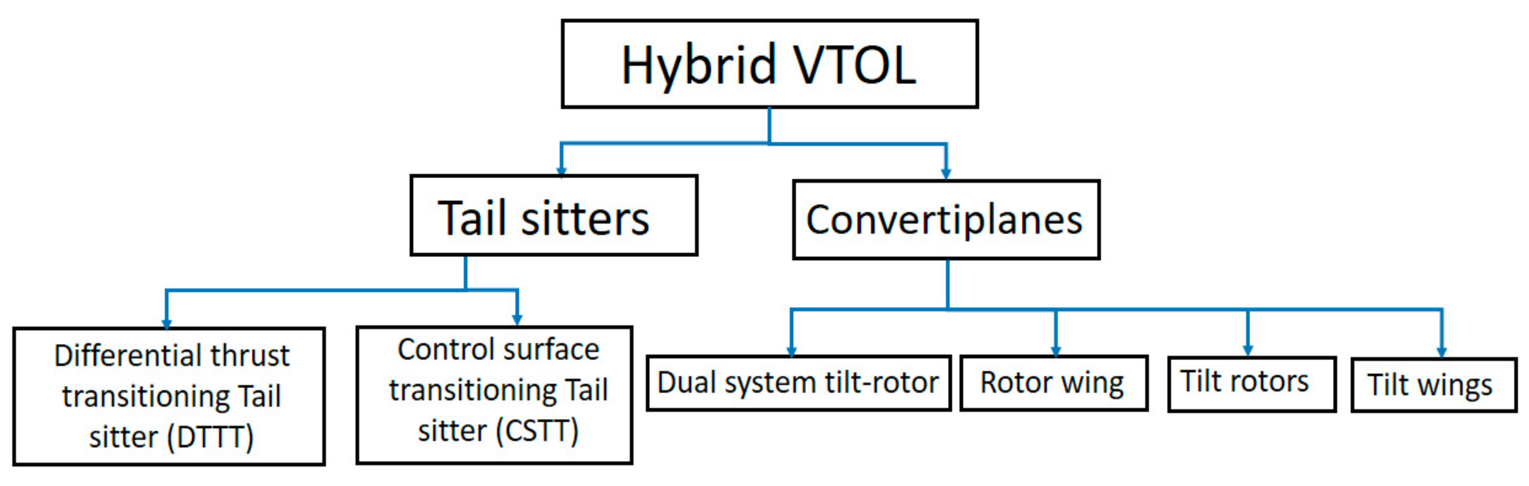
Figure 2. Isometric view of hybrid tilt-rotor.
Figure ii. Isometric view of hybrid tilt-rotor.
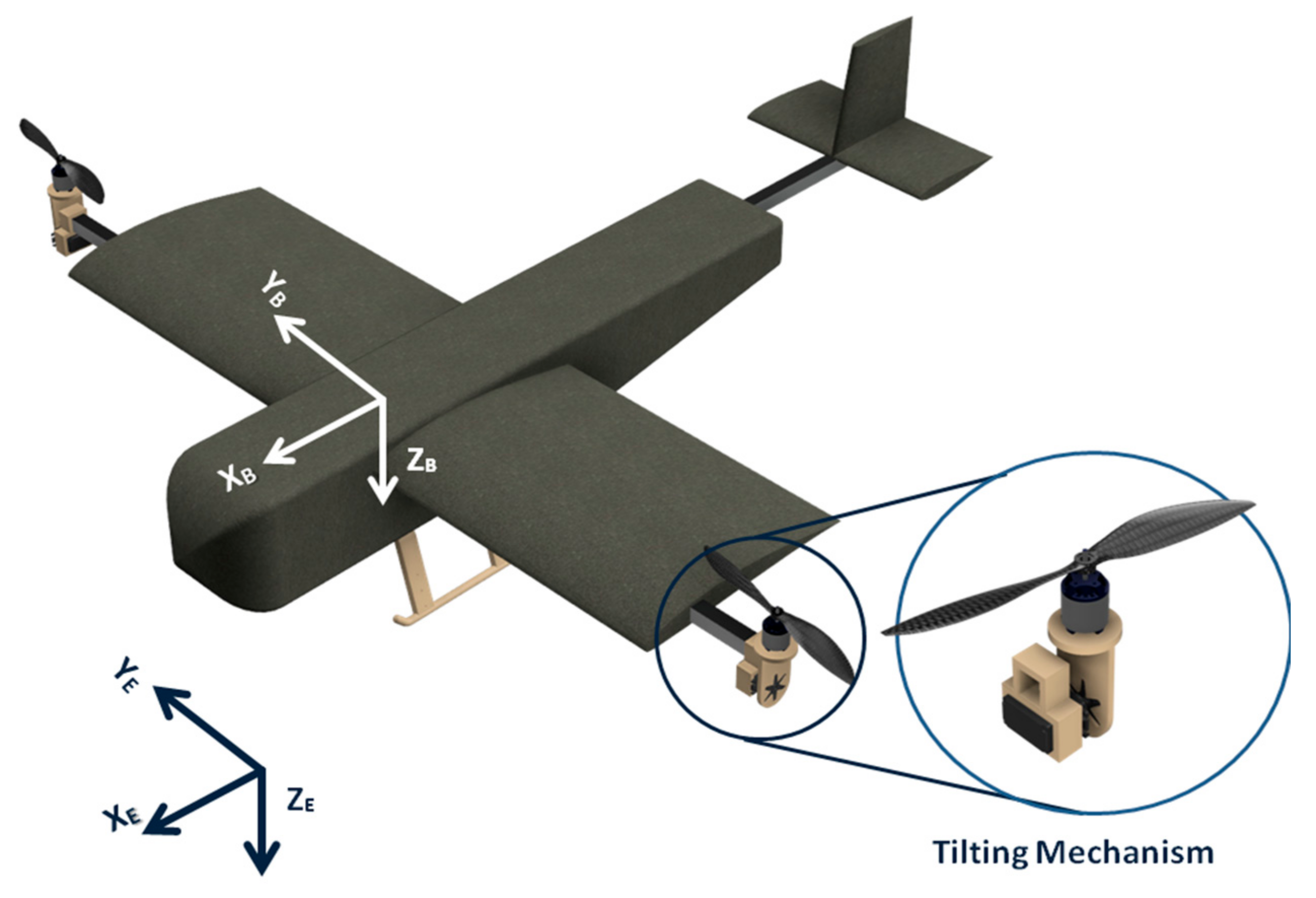
Figure 3. Iterations of the motor pod conceptual design.
Effigy 3. Iterations of the motor pod conceptual design.
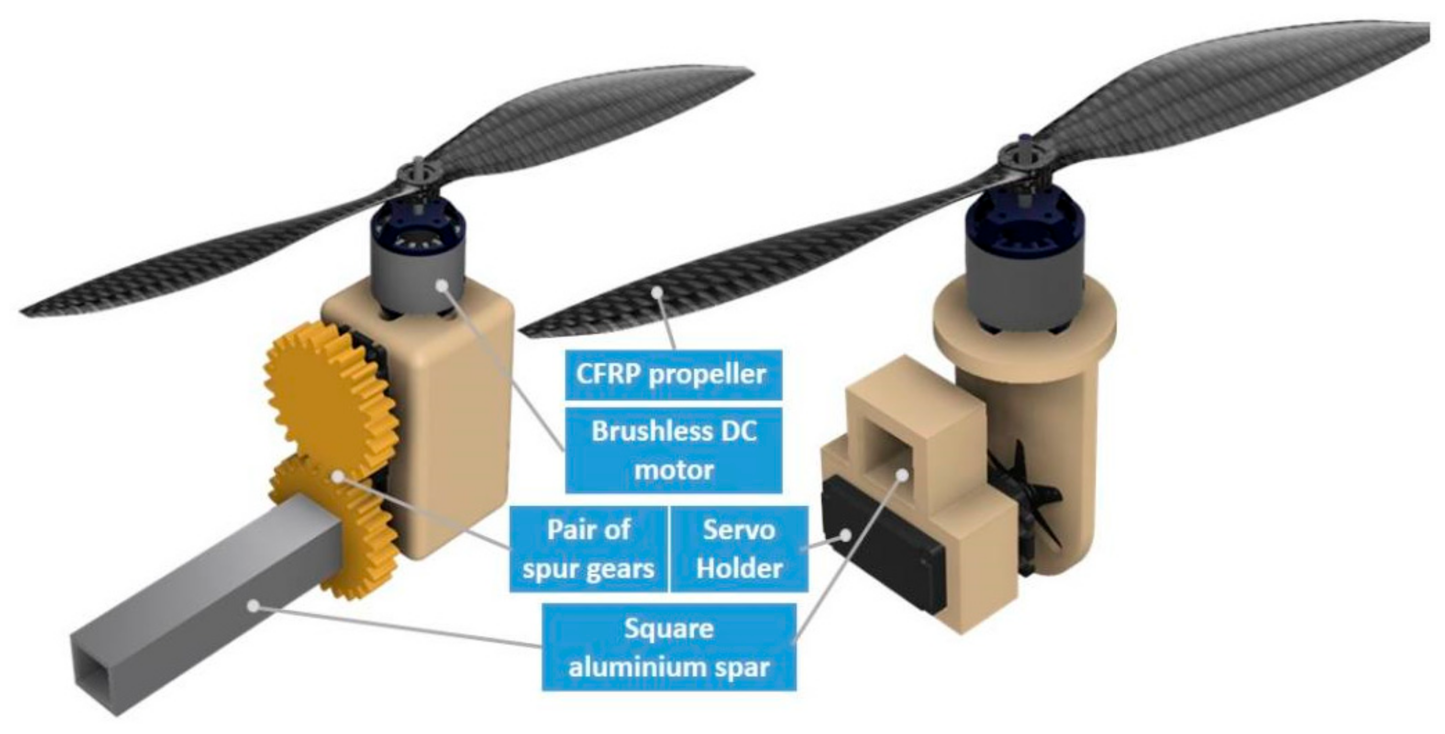
Figure iv. Isometric view of tilt-rotor during yaw, roll, and pitch in the VTOL flying phase. Here, (a) depicts the gyre configuration due to differential thrust, (b) depicts the pitch configuration due to tilting of the motor-pod and (c) illustrates yaw due to tilting of the motor-pod in opposite directions.
Figure 4. Isometric view of tilt-rotor during yaw, roll, and pitch in the VTOL flying stage. Here, (a) depicts the roll configuration due to differential thrust, (b) depicts the pitch configuration due to tilting of the motor-pod and (c) illustrates yaw due to tilting of the motor-pod in contrary directions.
Effigy v. Representative effigy illustrating the effective angle of attack.
Effigy 5. Representative figure illustrating the effective angle of attack.
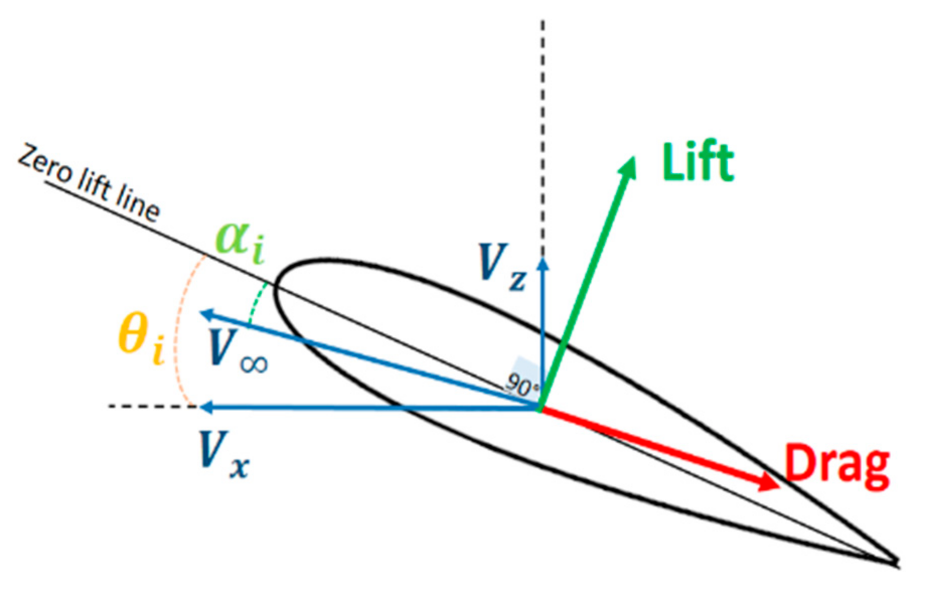
Figure 6. Mesh generated in the fluid medium for DAE 51 aerofoil.
Figure 6. Mesh generated in the fluid medium for DAE 51 aerofoil.
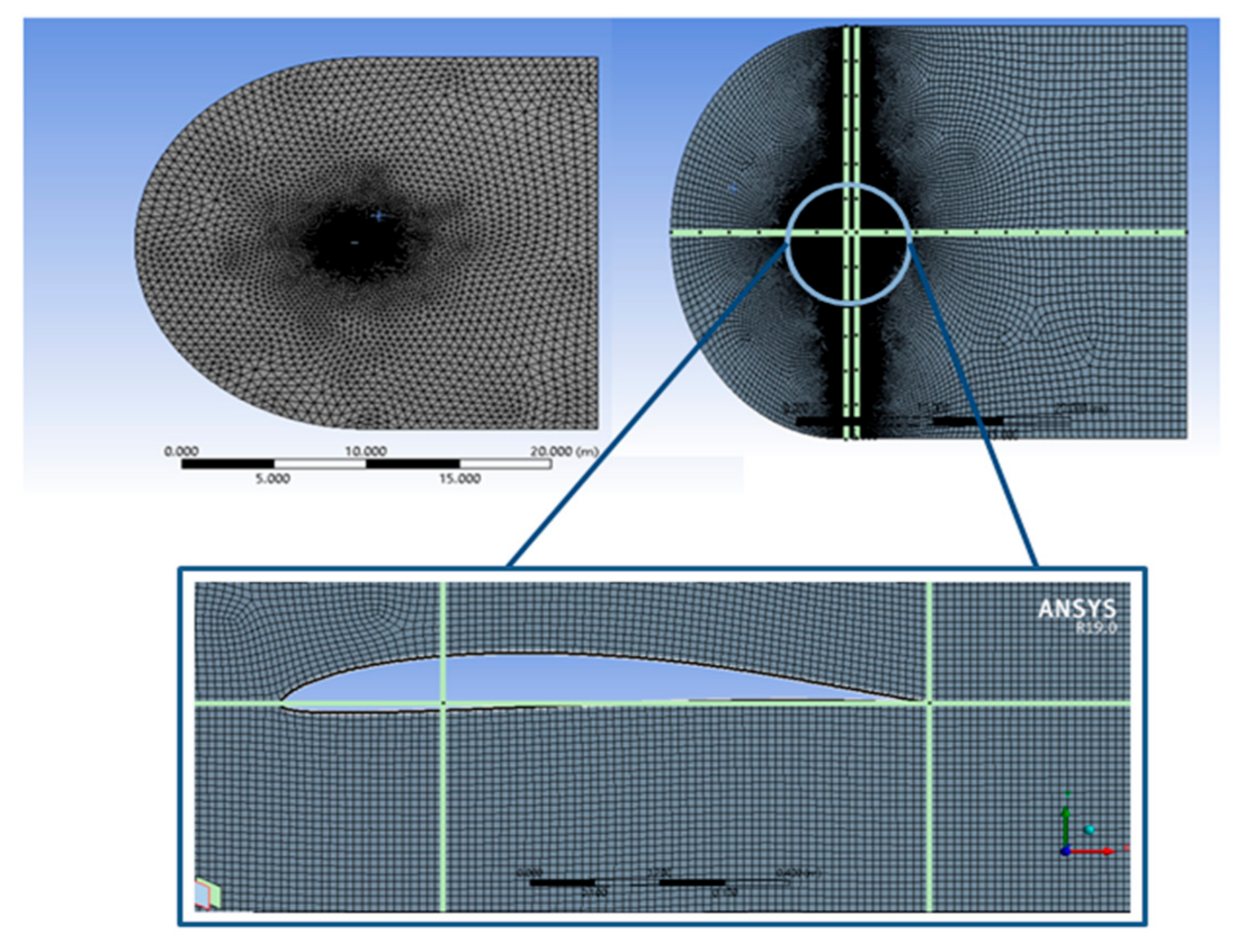
Figure vii. Variation of
and
with change in bending of assault.
Effigy 7. Variation of
and
with change in angle of attack.
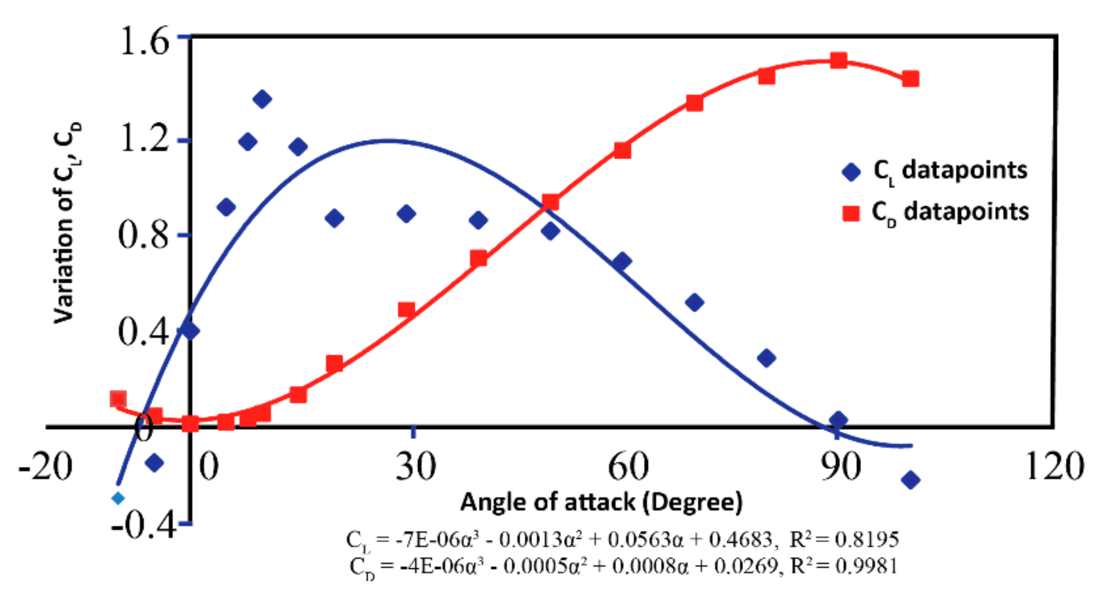
Figure 8. Contour plot of velocity vector for cruise conditions (fifteen m/s) at zero AOA.
Figure 8. Contour plot of velocity vector for cruise conditions (fifteen m/s) at zero AOA.
Effigy 9. Variation of lift and elevate forces with change in the AOA and airflow velocity.
Figure 9. Variation of elevator and drag forces with change in the AOA and airflow velocity.
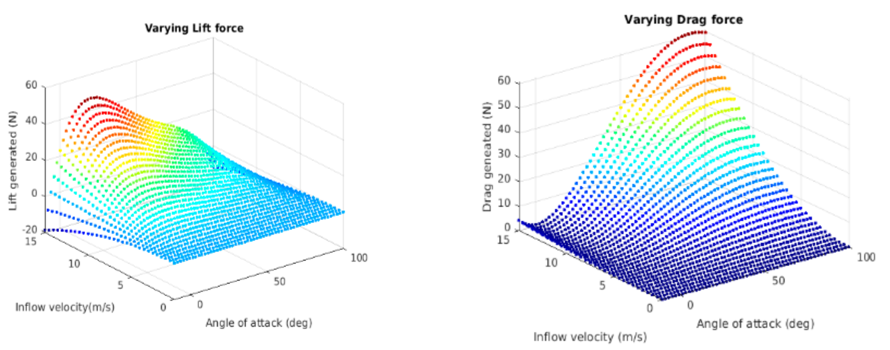
Figure 10. Hybrid VTOL tilt-rotor modeled in XFLR.
Figure 10. Hybrid VTOL tilt-rotor modeled in XFLR.
Effigy 11. Change in aerodynamic parameters due to elevator deflection. Here, subfigure (a) shows the variation of CD (Coefficient of drag), (b) shows the variation of CL (Coefficient of lift), (c) shows the variation of CFifty/CD, and (d) shows the variation of Cm (Coefficient of pitching moment) with varying angle of set on and fixed elevator deflection of 10°.
Effigy 11. Change in aerodynamic parameters due to elevator deflection. Here, subfigure (a) shows the variation of CD (Coefficient of drag), (b) shows the variation of CL (Coefficient of lift), (c) shows the variation of CL/CD, and (d) shows the variation of Cm (Coefficient of pitching moment) with varying angle of attack and fixed elevator deflection of ten°.

Effigy 12. Change in aerodynamic parameters due to aileron deflection. Hither, subfigure (a) shows the variation of Cfifty (coefficient of pitching moment), (b) shows the variation of Cn (coefficient of the yawing moment), (c) shows the variation of CL (coefficient of elevator), and (d) shows the variation of CD (coefficient of drag) with varying angles of assail and a fixed aileron deflection of 10°.
Figure 12. Modify in aerodynamic parameters due to aileron deflection. Here, subfigure (a) shows the variation of Cfifty (coefficient of pitching moment), (b) shows the variation of Cn (coefficient of the yawing moment), (c) shows the variation of CL (coefficient of lift), and (d) shows the variation of CD (coefficient of drag) with varying angles of attack and a fixed aileron deflection of 10°.
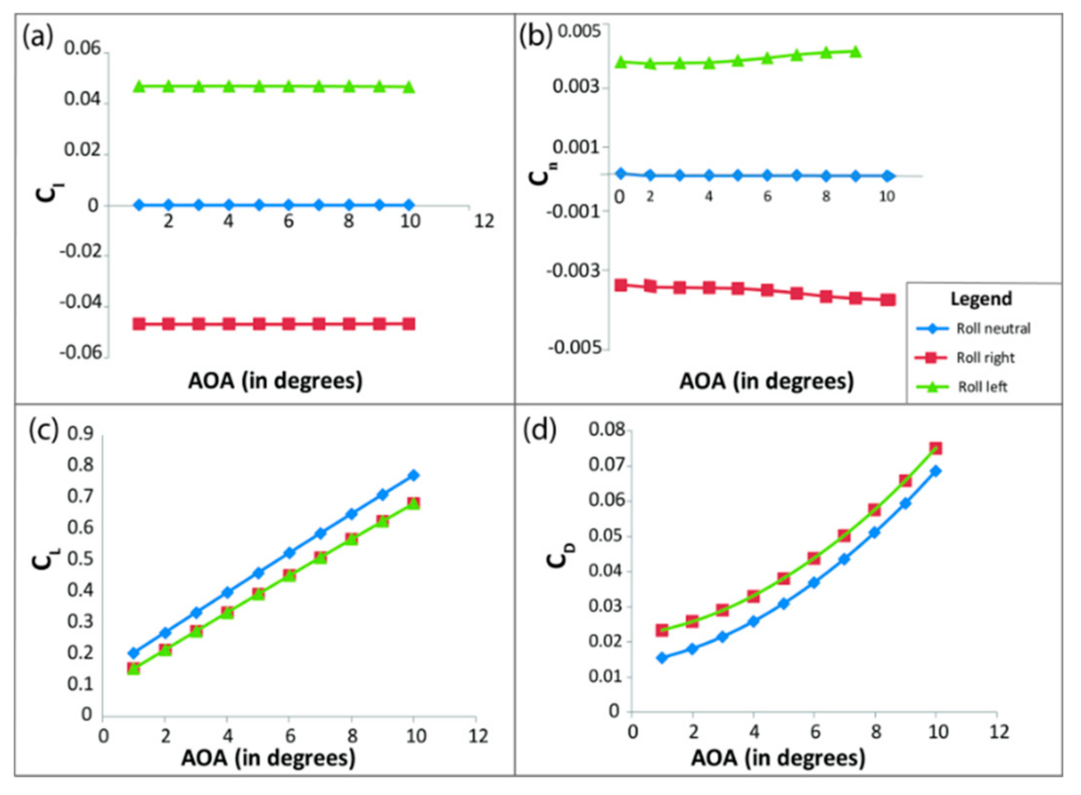
Figure thirteen. Modify in aerodynamic parameters due to rudder deflection. Here, subfigure (a) shows the variation of CY (coefficient of side force), (b) shows the variation of Cn (coefficient of yawing moment), (c) shows the variation of Cl (coefficient of rolling moment), and (d) shows the variation of CFifty/CD with varying skid angles and a fixed rudder deflection of ten°.
Effigy 13. Change in aerodynamic parameters due to rudder deflection. Here, subfigure (a) shows the variation of CY (coefficient of side strength), (b) shows the variation of Cn (coefficient of yawing moment), (c) shows the variation of Cl (coefficient of rolling moment), and (d) shows the variation of CFifty/CD with varying skid angles and a fixed rudder deflection of 10°.
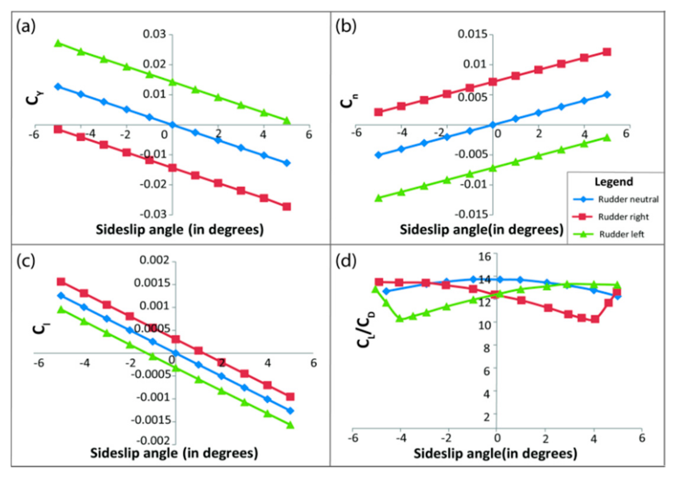
Figure fourteen. Arrangement model of hybrid VTOL tilt-rotor.
Figure 14. Arrangement model of hybrid VTOL tilt-rotor.
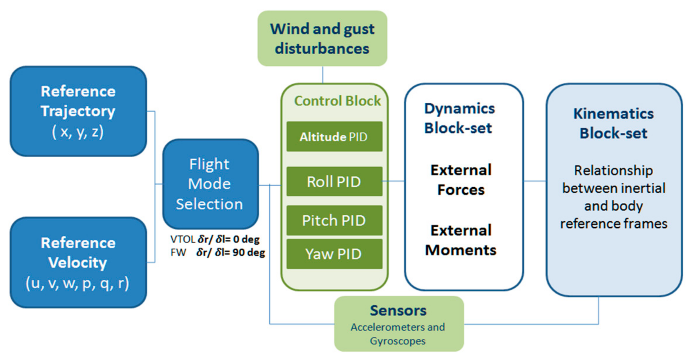
Figure 15. Trajectory tracking of hybrid VTOL vehicle.
Figure fifteen. Trajectory tracking of hybrid VTOL vehicle.
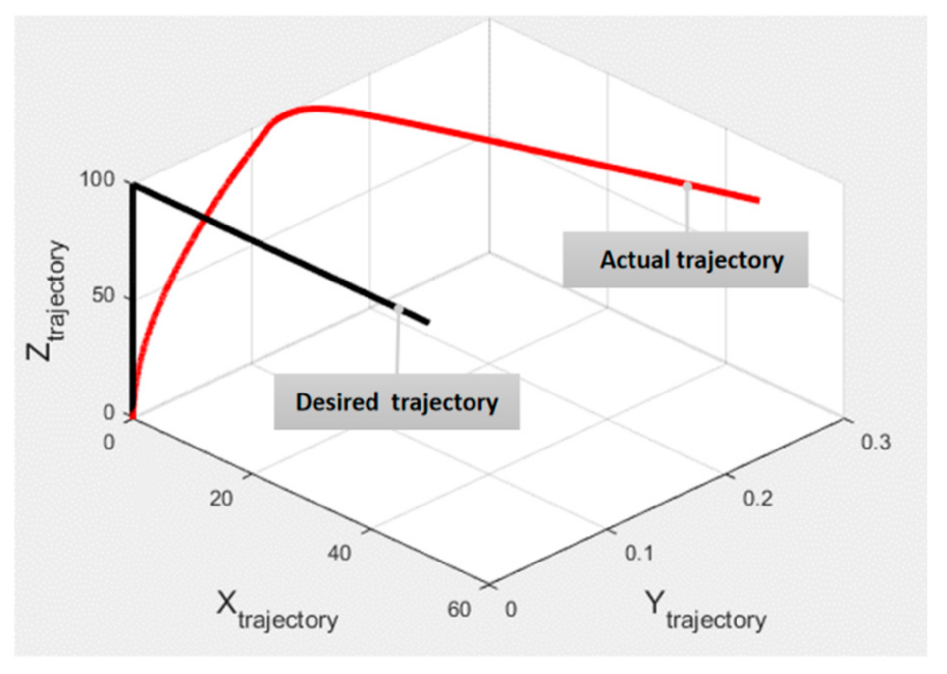
Figure 16. Variation of control parameters in the flying profile. Here, (a) shows the variation of the height and pitch angle along with the flight profile, and (b) shows the tilt of both the motor pods during the unabridged flight contour.
Figure 16. Variation of control parameters in the flight profile. Here, (a) shows the variation of the height and pitch angle forth with the flying profile, and (b) shows the tilt of both the motor pods during the entire flight contour.
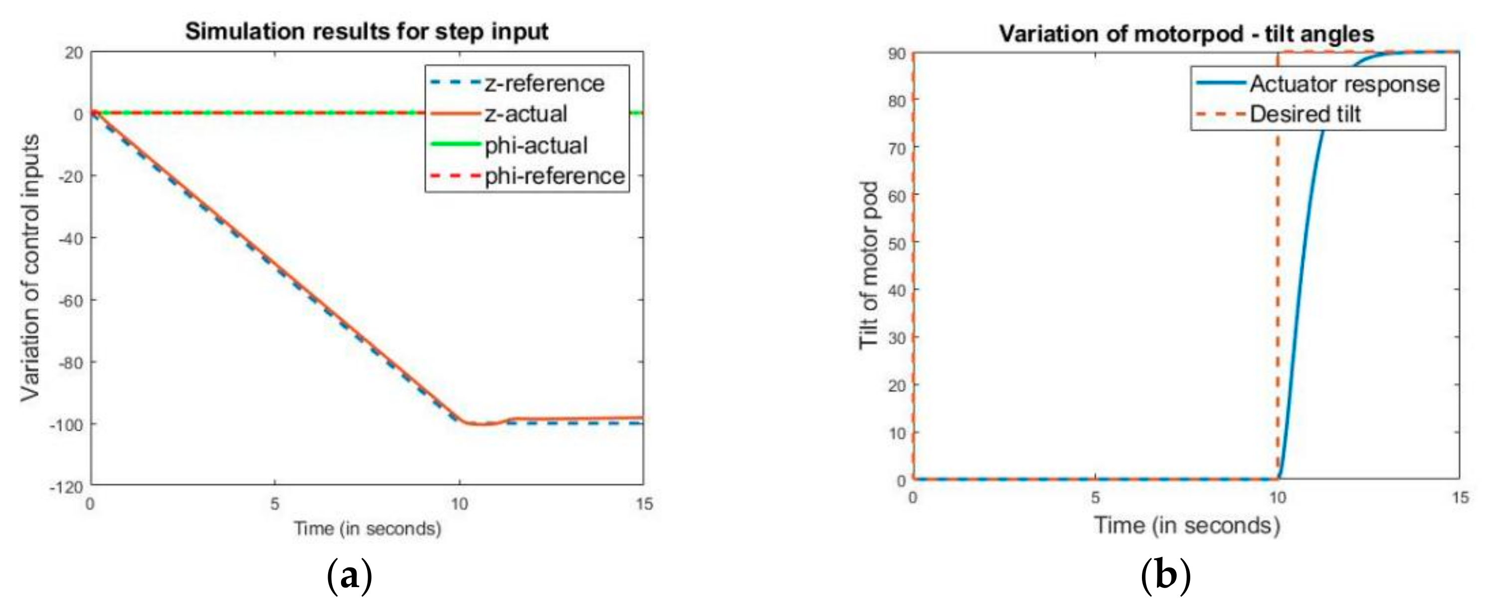
Figure 17. Experimental load prison cell setup for thrust calculation.
Figure 17. Experimental load cell setup for thrust adding.
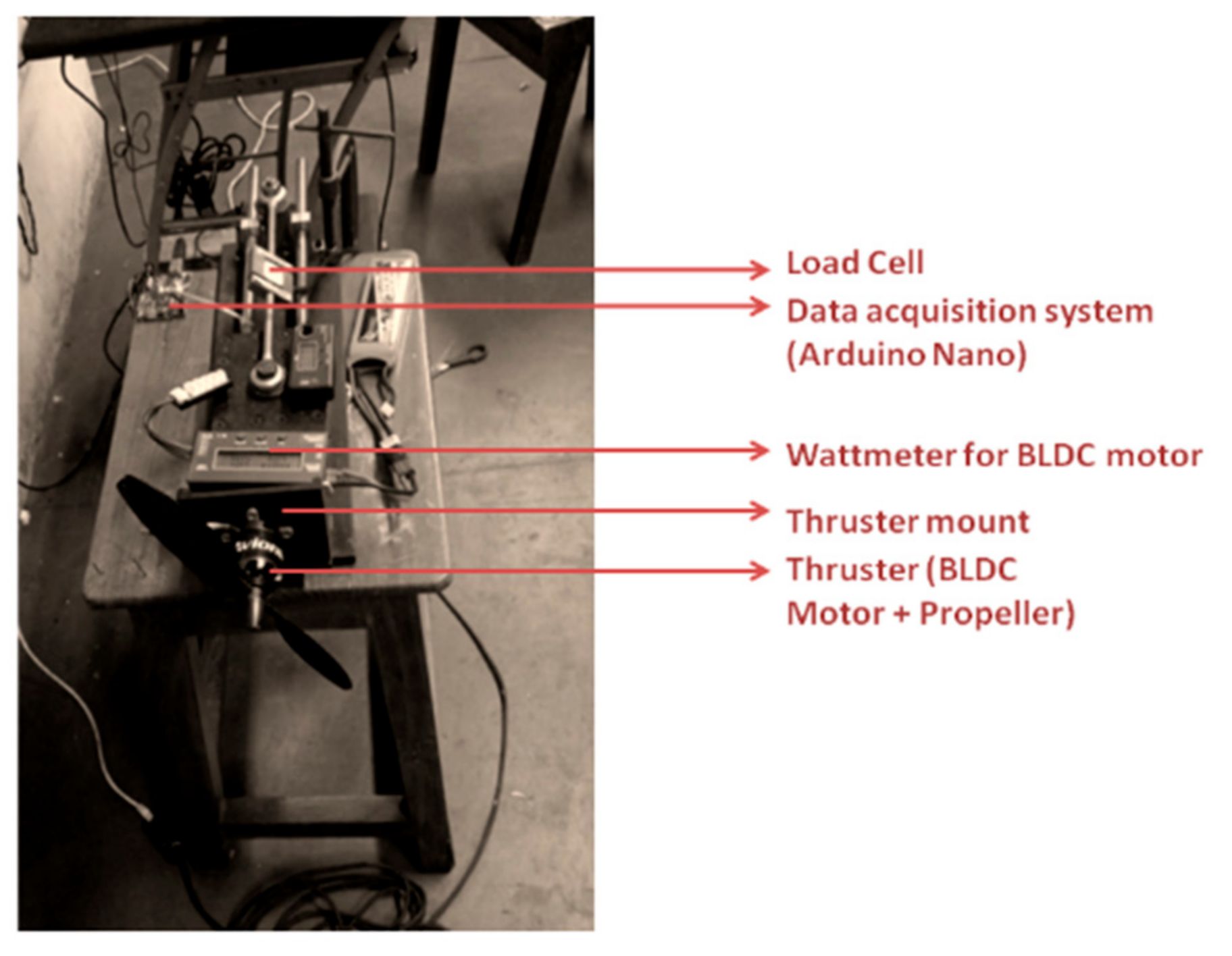
Figure 18. Fabricated prototype of the motor pod (Version1).
Figure xviii. Fabricated image of the motor pod (Version1).
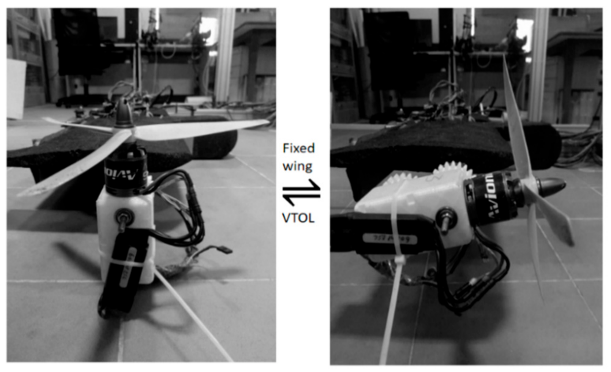
Figure 19. Schematic hardware implementation diagram.
Figure 19. Schematic hardware implementation diagram.
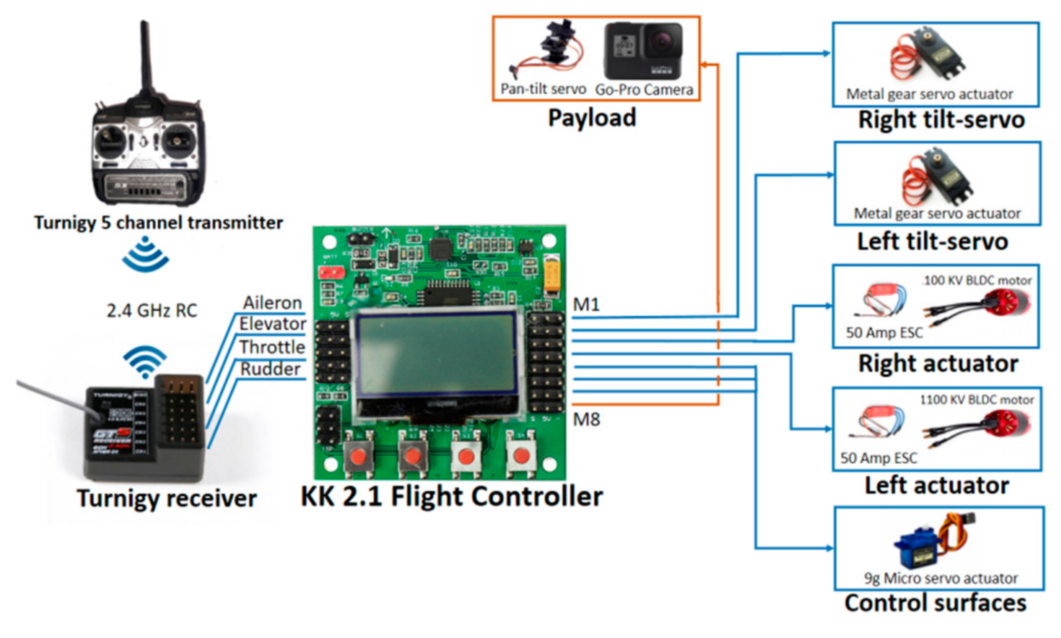
Figure xx. (a) Fabricated image of Hybrid VTOL tilt-rotor laying down the individual components and (b) the fabricated prototype of motor pod.
Figure 20. (a) Fabricated prototype of Hybrid VTOL tilt-rotor laying down the individual components and (b) the made paradigm of motor pod.
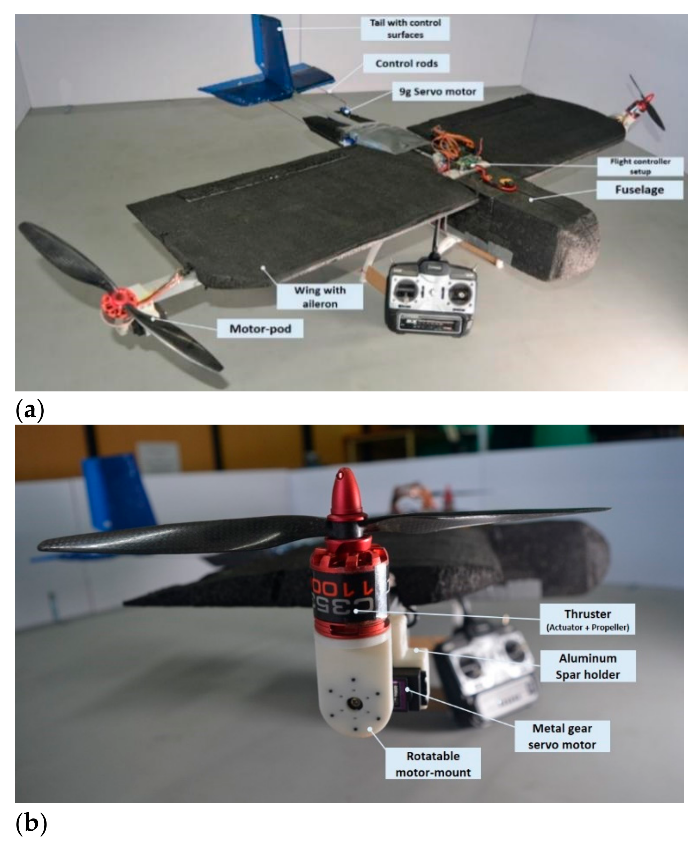
Table one. Mechanical design parameters specification.
Table one. Mechanical design parameters specification.
| Parameter | Specified Value |
|---|---|
| Configuration | VTOL Tilt rotor |
| Wing Span length | 110 cm |
| Wing chord length | 30 cm |
| Aero foil | DAE 51 |
| Overall weight/length/breadth | one.eight kg/110 cm/100 cm |
| Propeller diameter and pitch | 2 bladed 12″ × five″ |
| Center of gravity | 39 cm from nose of the aircraft |
| Inertia (Ixx, Iyy, Izz) | 0.1365 kg·thousand2, 0.04401 kg·m2, 0.1802 kg·one thousand2 |
| Moment of inertia of the rotor-pod (Irotor) | 0.050 kg·m2 |
Tabular array 2. Command inputs for various flight phases in hybrid VTOL tilt-rotor.
Table 2. Command inputs for diverse flight phases in hybrid VTOL tilt-rotor.
| Flying Stage | Desired Motion | M1 Tilt | M2 Tilt | Relation between ωR and ωL | Control Surface Input |
|---|---|---|---|---|---|
| VTOL | Heave | 0° | 0° | Increase or decrease proportionally ωR = ωL | Aught |
| Ringlet | 0° | 0° | Differential increment in athwart velocity ωR > ωFifty or ωL > ωR | Zero | |
| Pitch up | +ve | +ve | Same angular velocity in both thrusters ωR = ωL | Nil | |
| Yaw | −ve | +ve | Same athwart velocity in both thrusters ωR = ωL | Cypher | |
| Transition | Changing orientation of rotors | 90° | 90° | Aforementioned athwart velocity in both thrusters ωR = ωL | Zero |
| Stock-still Fly | Heave | ninety° | 90° | Increase or decrease proportionally ωR = ωFifty | Null |
| Roll | xc° | 90° | Same angular velocity in both thrusters ωR = ωL | Aileron input | |
| Pitch | 90° | 90° | Same athwart velocity in both thrusters ωR = ω50 | Lift input | |
| Yaw | 90° | xc° | Differential increase in angular velocity ωR > ωL or ωR > ωL | Rudder input |
| Publisher's Note: MDPI stays neutral with regard to jurisdictional claims in published maps and institutional affiliations. |
© 2021 by the authors. Licensee MDPI, Basel, Switzerland. This article is an open admission article distributed under the terms and weather of the Creative Commons Attribution (CC BY) license (https://creativecommons.org/licenses/by/4.0/).
Source: https://www.mdpi.com/1424-8220/21/18/5987/htm
Post a Comment for "A Review on the Platform Design Dynamic Modeling and Control of Hybrid Uavs"